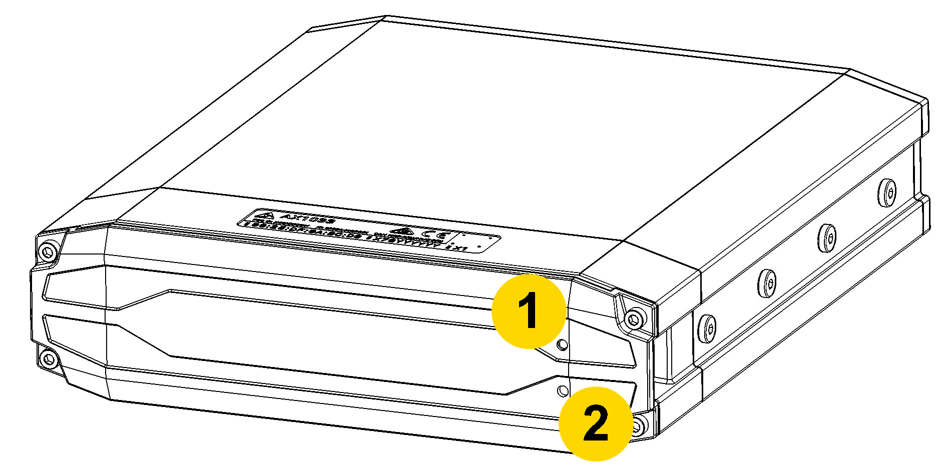
Component detail
Although your Axon Fleet 3 system can be configured for automated transfer from Buffering to Event (recording) mode under the right conditions, the Dual-View camera still includes physical controls to enable recording. Additionally, the camera will also provide visual and audible notification of the Axon Fleet 3 system's state of operation.
Many of the features activated by the buttons below also can be activated in Fleet Dashboard (see user guide on the Fleet 3 product page at my.Axon.com).
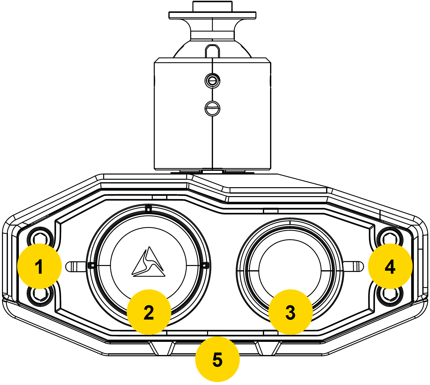
Camera front
|
|
|
|
|
|
- Power cable – Provides power from Fleet Hub.
- Ball joint – Attaches camera to camera mount. The camera supports pan, tilt, and roll. To restrict any of these, tighten the screws. For general use, tighten the roll and tilt screws and leave the pan set screw loose.
- Evidence lens – Lens for recording evidence.
- Operation indicator – Indicates camera recording status.
- ALPR lens – Lens for Automated License Plate Recognition (ALPR) processing.
Dual-View camera (DVC) pan and tilt
The Axon Fleet 3 Dual-View camera's joint lets you pan and tilt to capture objects of interest otherwise camera’s field of view. The ball joint has detents that click and hold the camera at every 22.5 degrees horizontal pan.
For ALPR use, Axon recommends the following positioning:
- In most situations, including typical roadway patrol, aim the camera directly forward. The ALPR lens will cover three lanes: the lane in-front and the lanes on either side of the vehicle.
- When patrolling parking lots with either perpendicular or diagonal parking, pan the camera to the 22.5- or 45-degree detents to better capture plate information.
- When parked roadside, panning the camera to the first off-center detent of 22.5 degrees will cover an additional lane of traffic: the lane in front and two lanes adjacent to the same side.
See ALPR system use case recommendations on my.Axon for additional details on camera positions.
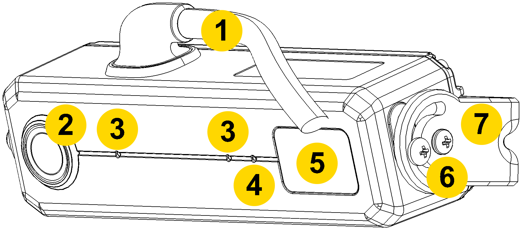
Camera rear
- Primary LED – Indicates the Dual-View camera's current operating status.
- Primary button – Use to manually start and stop recording for Dual-View camera.
- Secondary button – Use to manually start and stop recording for interior camera.
- Secondary LED – Indicates the interior camera's current operating status.
- Microphones and speaker on bottom – Provide full audio ability.
The primary LED displays operating status of the front Dual-View (DV) camera. The secondary LED displays operating status of the interior (Int.) camera.
| Camera Status | LED Behavior | Camera |
|---|---|---|
| Buffering |
 Solid green Solid green
|
DV & Int. |
| Camera updating |
 Blinking white Blinking white |
DV & Int. |
| Error encountered |
 Blinking yellow Blinking yellow |
DV & Int. |
| Livestreaming while buffering |
 Blinking purple Blinking purple |
DV |
| Livestreaming while recording |
 Blinking red and purple
 |
DV |
| Powering on |
 Rapid blinking green Rapid blinking green |
DV & Int. |
| Recording |
Blinking red |
DV & Int. |
| Installing firmware update |
 Alternating white LEDs (#1 and #4 in preceding image) Alternating white LEDs (#1 and #4 in preceding image) |
DV |
Watch this video for an overview of the Fleet 3 camera LEDs.
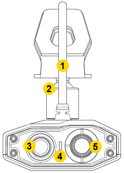
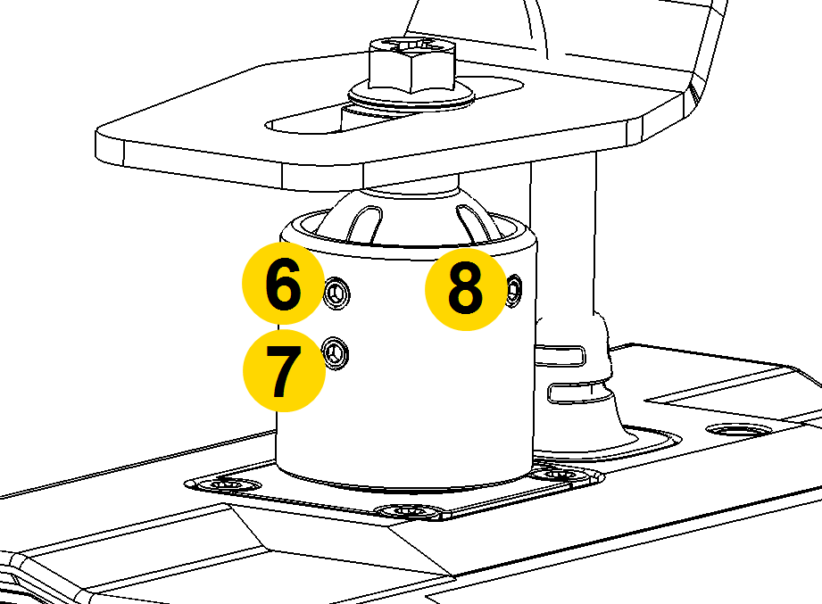
Interior camera
- Cable – Connects the camera to the camera controller.
- Lens – The camera lens.
- Microphone – For recording in-cabin audio.
- Ambient light sensor – Engages infra-red (IR) illumination at low ambient light.
- IR illumination window – Infrared (IR) illumination source.
- Angle adjustment screws – Allows adjustment of camera tilt.
- Mount – Attaches camera to the vehicle.
Camera zoom
The camera zoom works in both Buffering and Event modes to magnify the image shown in preview.
- In the Fleet Dashboard, select Full-screen
 on the desired camera title.
 - Tap anywhere on the screen to magnify that area by 2x. Tap again for 4x or use the slider on the right. Magnification returns to normal 10 seconds after your last tap.
- Tap Lock
 to stop the 10-second countdown. If Hold is used during recording, magnification returns to normal when the recording stops.
 - Tap Full Screen
 to return to the dashboard.
Hub
- LED – Indicates the hub’s current operating status.
- Restart button – Use as described in Troubleshooting.
Audio prompts
The Fleet system emits beeping audio prompts to indicate system status. These audio prompts usually occur after a camera action.
| Operating Mode | Audio Notification | |
|---|---|---|
| Powering on or off |
 |
One tone |
| Recording an event |
|
Two tones every two minutes |
| Mute on or off |
|
Two tones |
| The device is ending an event and returning to Buffering mode |  |
One long tone |
| Respond Livestreaming started |
  |
Three rising pitch tones |
Summary of button presses
The primary and secondary buttons on the Fleet 3 Dual-View Camera (DVC) performs multiple functions depending on the number and duration of presses. The primary button operates the DVC; the secondary button operates the interior camera(s).
|
|
Secondary | Duration | Result |
|---|---|---|---|
| Single press* | <3 sec. | Start or stop recording, as applicable | |
| Double press | <1 sec. | Start recording | |
| Long press | 3–8 sec. | Stop recording | |
| Very long press | n/a | >8 sec. | Stop recording after 3 sec. (system reboot message sent at 8 sec. mark even if button is not released) |
| Triple press | n/a | <1.5 sec. | Firmware installation begins when the DVC displays alternating blinking LEDs |
* A single press from the same button must occur more than one second apart. Another single press within one second will be discarded.