Introduction
The pole installation procedures described here are generally applicable to most temperate environments. Defer to local professionals for best practices for your physical environment; installing a pole in Florida will differ from installing one in Alaska.
Only qualified technicians should perform tasks related to connecting to AC power.
Read these instructions completely before starting assembly and installation. If you have questions, contact our support team at my.axon.com/s.
Tools you'll need
| Tool | Purpose |
|---|---|
| Power drill | Driving sockets |
| Sockets (with drill attachment): 8, 10, and 13 mm | Tighten bolts on solar panel brackets, camera mounts, and hose clamps |
| 7/32" step up drill bit | For 100W panels, to drill mounting holes |
| Marking tool | For 100W panels, to mark drill holes |
| Wire strippers | For trailer installs, strip wire to make electrical connections |
| Crimpers | For trailer installs, crimp butt-splices and fork terminals |
| Rubber mallet | Move components into place |
Supplies you'll need
You'll need these expendable parts that are not included.
| Item | Approx. Qty | Purpose |
|---|---|---|
| Hose clamps - various diameters | 2 | For mounting camera or solar panel side mount to variety of existing poles |
| Zip ties | Depends on install | Wire management |
| #10 flat washers | 4 | For 100W panels, to mount solar brackets |
| Butt connectors, 16-14 AWG, blue | 2 | For trailer installs, splicing camera power cable |
| Assorted ring and fork terminals | 2 | For trailer installs, terminating camera power cable |
Package contents
| Part Name | Qty | SKU | Image | Note |
|---|---|---|---|---|
| Outpost camera | 1 | 102032 | 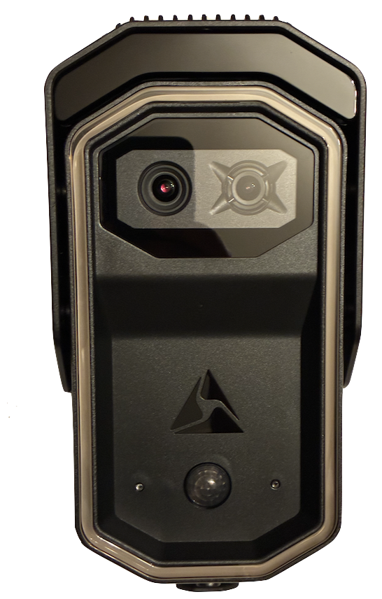
|
Outpost Camera |
| Outpost camera, solar power cable, 1 m | 1 | 102542 | 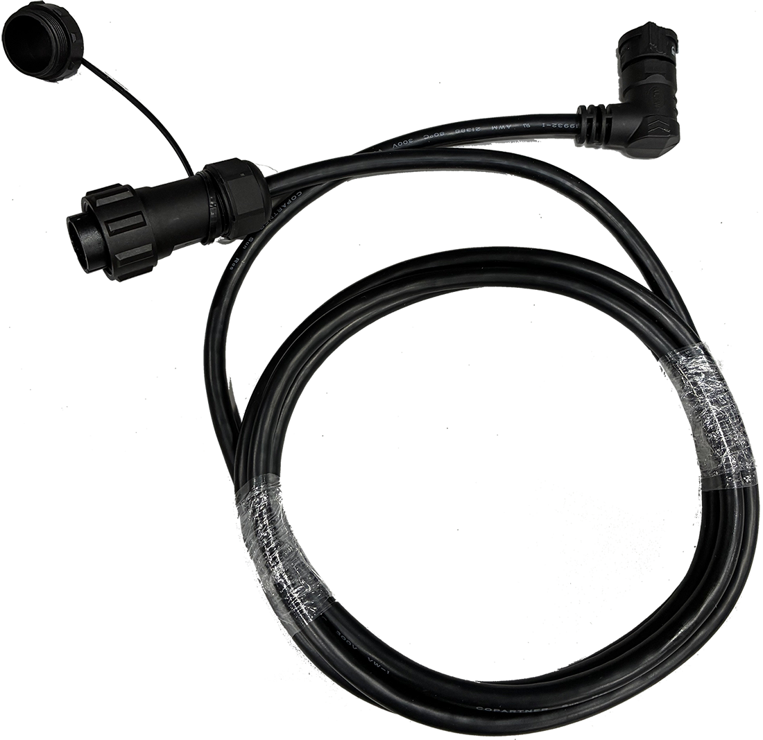
|
Used in solar installs |
| Outpost camera, unterminated power cable, 4 m | 1 | 102537 | 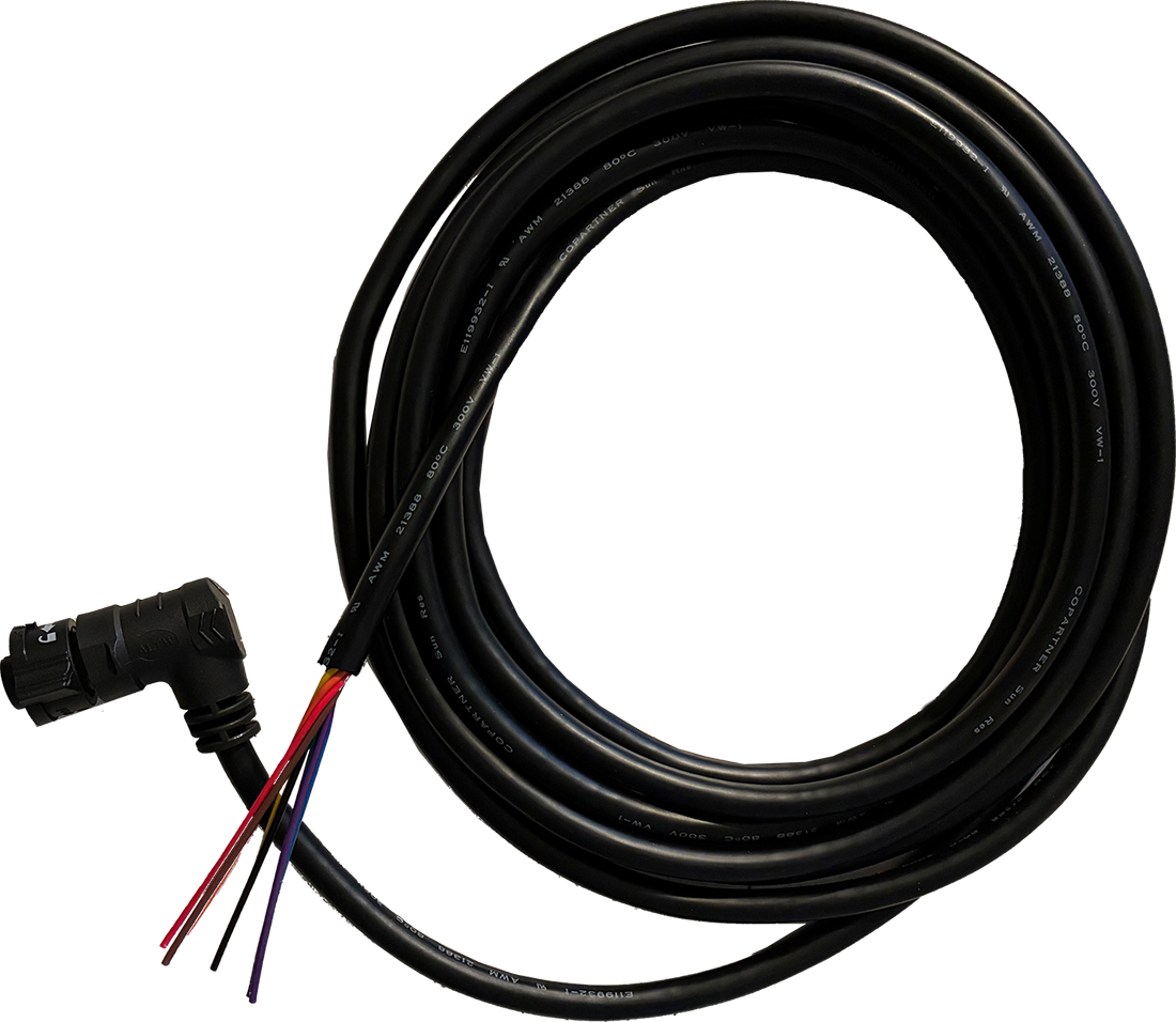
|
Used in non-solar installs |
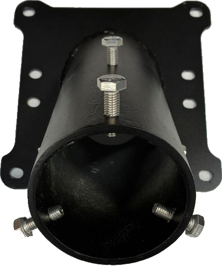
| Outpost camera pole mount | 1 | 102536 | 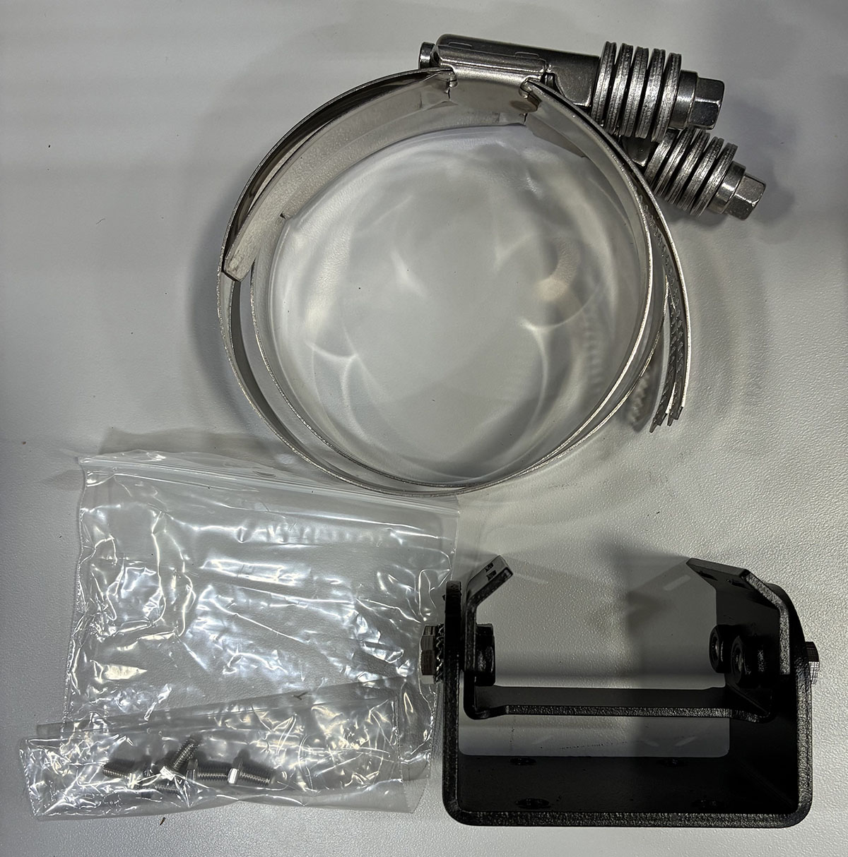
|
Camera pole mount |
| Outpost camera wall mount | 1 | 102546 | 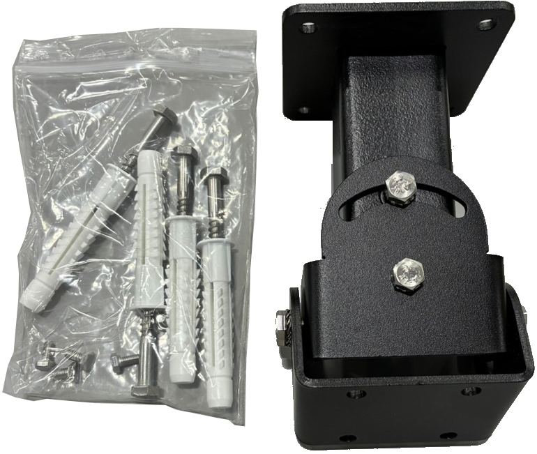
|
Camera wall mount |
| Solar panel (50 or 100 W) | 1 | 102487 (50 W), 102488 (100 W) | 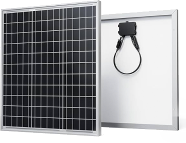
|
Solar panel |
| Solar panel bracket set | 1 | 102539 | 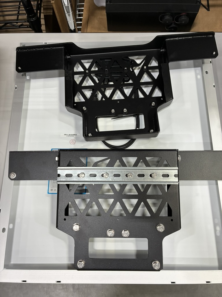
|
Set of two pieces |
| Top mount end cap | 1 |
102538 Standard 3"; 102545 Mash 4.5" diameter |
|
End cap for Axon poles |
| Battery enclosure | 1 | 102126 Standard; 102543 Extended | 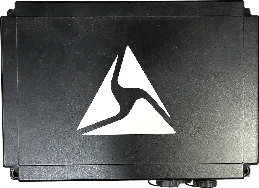
|
Enclosure containing external battery and charge controller |
| Solar panel cable | 1 | 102544 | 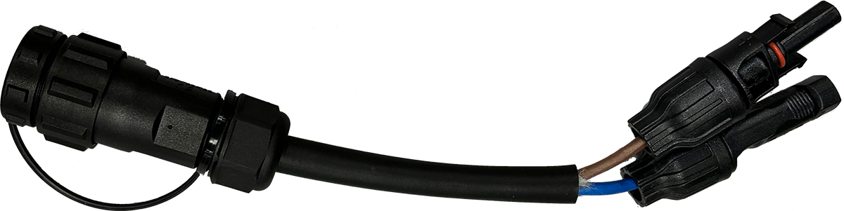
|
Connects solar panel to enclosure |
| Side mount kit | 1 | 102541 | 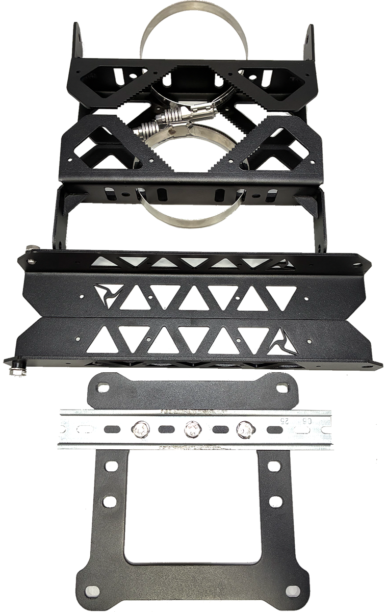
|
Hardware to mount solar panel to existing infrastructure |
| Outpost camera, AC power supply, outdoor | 1 | 102547 | 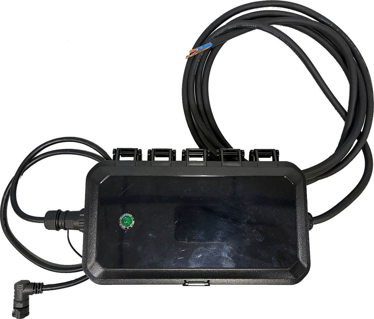
|
Receives AC power and supplies DC to the camera |
Site selection and mounting guidelines
We recommend the following practices for site selection and camera set-up:
- Read range and roadway placement: The camera’s maximum read distance is up to 75 ft and it supports a minimum of 2-lane capture when installed with appropriate placement and aim. Actual performance depends on how the camera is positioned relative to the roadway, including setback from the road edge, mounting height, and distance to the farthest lane to be captured. When planning placement, ensure the target lanes have a clear line of sight and that the farthest lane falls within 75 ft of the camera.
- Reflective signage (nighttime IR): At night, the camera uses infrared (IR) illumination. Avoid placing the camera where highly reflective signs or materials (stop signs, speed limit signs, reflective barricades, etc.) are within the camera’s primary field of view near the roadway. These surfaces can reflect IR back toward the camera and may cause glare/overexposure during passing vehicles, reducing plate capture/read performance. If reflective signage is unavoidable, adjust placement and aim so it is outside the primary viewing area.
- Aiming the camera: Use the Axon Outpost Manager mobile app during installation to confirm camera positioning, field of view, and aim. This helps validate roadway coverage and minimize reflective surfaces in view.
- Recommended mounting height: Install the camera 10–12 ft above ground. Mounting above or below this range may reduce capture/read performance due to less optimal viewing angles.
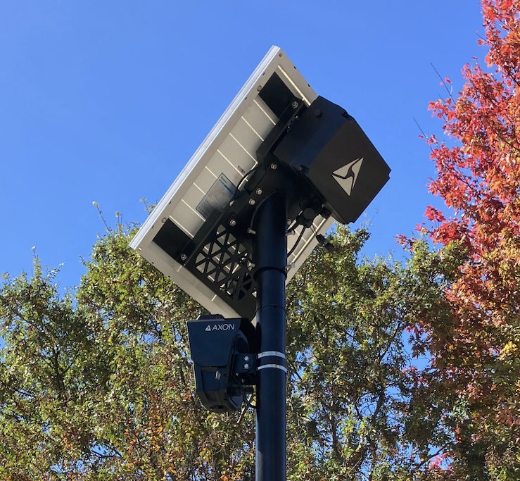
- Solar-powered site considerations: For solar-powered installations, choose a location where the solar panel can face generally south and receive unobstructed sunlight throughout the day. Avoid placement where the panel may be shaded by trees, buildings, overhangs, light poles, or signage, especially during winter months when the sun is lower. Shading can reduce charging performance and may impact system uptime.
- Avoid solar panel IR flare: If the camera is mounted beneath or near the solar panel, the camera’s nighttime IR illumination can reflect off the panel surface and create glare in the image, which may reduce plate capture/read performance. To prevent this, mount the camera so it sits far enough below and/or offset from the panel that the panel is not directly in front of the camera’s IR output. As a rule of thumb, ensure the camera-to-panel separation is greater than the length of the nearest panel mounting arm/bracket, and add a small safety margin to account for hardware and tolerances. If glare is observed at night, reposition the camera lower or farther away from the panel, or adjust the panel/camera placement to eliminate reflective surfaces in the camera’s primary viewing area.